Following the principle of "fixed before moving, large before small, and difficult before easy", priority is given to laying out important unit circuits and core components with fixed positions. For components that require positioning, such as tooling holes, connectors, etc., they are assigned an immovable attribute and their dimensions are labeled.
Temperature sensitive components should be kept away from heat generating components; Components with high heat generation should be placed at the air outlet or in a location conducive to convection. Components with high heat generation should be placed at the air outlet without blocking the air duct; The radiator should be placed in a location that is conducive to convection.
Decoupling components should be placed near the power input end. RF chips are very sensitive to power noise, so each chip uses some capacitors and shielding inductors to ensure that all power noise is filtered out. It is required that the filtering components be placed near the chip to ensure good filtering before power input, otherwise the noise will radiate to the entire PCB side.
Refer to the schematic diagram and layout the main components according to the important (critical) signal flow direction.
When laying out, try to meet the following requirements: the overall wiring should be as short as possible. The main signal line must be the shortest. The fewer through holes, the better. Thoroughly isolate high voltage and high current signals from low voltage and low current weak signals; During design, analog signals and digital signals need to be separated; Of course, high frequency and low frequency should also be separated; The spacing between high-frequency components should be sufficient.
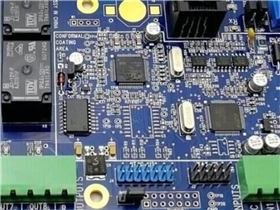
The crystal oscillator should be placed closest to the chip, but not near the edge of the circuit board.
Inductors or magnetic beads cannot be placed side by side. If they are placed side by side, they will form hollow transformers and cause interference signals due to mutual induction. The distance between them should be at least greater than the height of one of the components or placed at a right angle to minimize mutual inductance.
Symmetric layout should be adopted as much as possible for voltage divider circuits, differential circuits, and circuit parts with the same structure; Put components with the same power supply together.
On the premise of meeting electrical performance, optimize the layout according to the principle of uniform distribution, balance the center of gravity, and try to be as beautiful and neat as possible.
Your trusted partner and one-stop supplier for FPC/PCB manufacturing, component procurement, FPC/PCB assembly, and electronic manufacturing. With over 16 years of experience, we have been providing high-quality FPC/PCB at competitive prices to over 1000 customers worldwide. Our company has passed ISO9001:2015 certification and UL certification, and all of our products have undergone 100% electronic testing and passed AOI and X-RAY inspections to meet the highest industry standards. Therefore, please obtain an immediate quote from our sales team as we will handle the remaining matters.
Haibo is an expert in the field of FPC/PCB manufacturing and surface mount assembly in China. Since our establishment in 2017, we have been providing high-quality PCBs to over 1000 customers worldwide. Our factory has passed ISO14001, ISO9001:2015, TS16949, and ISO13485:2016 certifications. We are one of the most trusted small and medium-sized FPC/PCB manufacturers in China.